The Power Of Paint
Look at the RNAV (GPS)–A approach at Naples, FL (KAPF). Seems like it is a straight-in approach to Runway 32 but it only has circling minimums. There are three conditions…
Certain runway markings are required for each of the classifications of runway service.
Look at the RNAV (GPS)–A approach at Naples, FL (KAPF). Seems like it is a straight-in approach to Runway 32 but it only has circling minimums. There are three conditions stated in the FAA Instrument Procedures Handbook (FAA-H8038-16B) preventing straight-in minimums: 1) The final approach course alignment with the runway centerline exceeds 30 degrees, which isn’t the case here. 2) The descent gradient is greater than 400 feet/NM from the FAF to the threshold crossing height (TCH). The actual descent gradient here is 316 feet/NM. 3) A runway is not clearly defined on the airfield. This is all that’s left.
The FAA interpretation is that Runway 32 does not have instrument-runway markings; i.e. lacks the “paint” to make the runway clearly defined. Of course, lack of straight-in minimums doesn’t prevent a straight-in landing, so long as you use the circling minimums.
There are many important aspects to instrument flying, but it’s unlikely that runway markings make the top 100. Why? Perhaps because we take the paint for granted, just like stale coffee at the FBO.
Take-Off Visibility Mins
Part 91 pilots are not bound by published take-off minimums like commercial operations are. But for risk mitigation purposes we should at least consider them. At St-Petersburg-Clearwater, FL airport (KPIE), minimum take-off visibility for Runways 18 and 36 is an RVR 5 (500 feet) if centerline lights (CL) and high intensity runway lights (HIRL) are operating. However, with only CLs or runway centerline markings (RCLM) and HIRL, the takeoff visibility increases to 1000 feet (RVR 10). RCLM are the “paint,” the dashed line down the center of the runway. With a higher visibility, specifically RVR 16 or ¼ SM, “Adequate Vis Ref” is needed. Even though the FAA does not define “adequate visual reference,” presumably it refers to the ability to keep the airplane on the centerline during the take-off roll using visual references. Otherwise without adequate visual reference, the standard visibility of ½ SM or 1 SM applies, depending on number of engines.
Landing Minimums
We’ve already seen how lack of “adequate runway markings” means an otherwise straight-in approach will only have circling minimums. Now, let’s take a closer look at what all that paint actually means.
Because RWY 14/32 at Naples does not have instrument markings, it is considered a “VFR” runway requiring circling MDAs. The matrix below summarizes what runway markings are needed for different types of approaches.
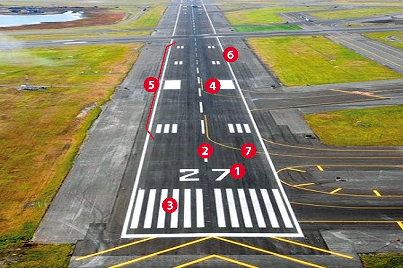
For a typical precision instrument runway, markings are as follows:
1. Designator, otherwise known as “the runway number,” usually aligned to the nearest 10 degrees magnetic. However sometimes to distinguish between parallel runways, the rule is not always followed. For example, Chicago O’Hare has Runways 9L, 9R, 10L, 10C, and 10R, all with an alignment of 93.5 or 93.6 degrees magnetic. And with the ever shifting isogonic lines resulting in magnetic deviation changes, peri‑ odically the “numbers” have to be changed.
2. Runway Centerline Markings were our nemesis during primary training. We were supposed to place the nose wheel on the centerline during landing and keep it there as we rolled down the runway before turning off to a taxiway. CAT II and III approaches usually also have embedded runway centerline lights to aid in very low visibility conditions. (As an aside, the current standard is that the length of a centerline marking is 120 feet and 80 feet between stripes. This means that the start of a stripe to the start of another stripe is 200 feet which makes it convenient for pilots preparing for the commercial SEL practical for the Power-Off 180° Accuracy Landing. However, the standard length is not always applied to VFR-only runways.)
3. Threshold Markings help us to identify the beginning of the runway. It should not be confused with the threshold itself which would be a white line or at night, identified by green lights as seen from the approach side.
4. Aiming Points are the big white rectangles that technically indicate where an electronic glide slope would run into the ground. Since they are 150 feet long, they are great references for VFR short field landings.
5. Touchdown Zone marks the touchdown zone which could, at times, depending in runway length, include about a third of the runway and sometimes also could have embedded lights.
6. Runway Edge Markings delineate the lateral boundary of the runway and help to distinguish where the pavement ends and the grass starts.
7. Taxi-line markings indicate the taxi path to and from the runway.
Crossing Runways
When runways cross, the paint is modified based on an order of precedence, meaning that runways associated with lower decision altitudes (DA) take precedence over other runways. Let’s look at an example. San Francisco Airport (KSFO) has two sets of parallel runways. Runway 28L has an ILS CAT II approach whereas Runway 28R has ILS CAT II & III approaches. The intersecting Runways 19L and 19R have either an ILS CAT I or RNAV (GPS) approaches. The order of precedence is CAT III, CAT II, CAT I, non-precision and visual. For these purposes RNAV (GPS) are considered non-precision even if they have an electronic glideslope with LPV DAs.
So, with Runways 28L and 28R taking precedence because of the higher-precision approaches, notice how the paint clearly looks like those runways are on top of the crossing runways.
Additionally, if a runway has a precision approach to one end, but a non-precision approach to the other end, both ends will have precision markings. (It’d look rather odd if it didn’t.)
Other Markings
Our focus is mainly runway markings where aircraft can land and take-off, but there are other markings associated with runways.
There is another type of surface associated with a runway—usually blast pads or stop ways marked with yellow chevrons. One type of stopway is Engineered Material Arresting Systems (EMAS). EMAS are “high energy absorbing materials of selected strength, which will reliably crush under the weight of an aircraft.” If any aircraft goes into an EMAS area, it won’t be taxiing away anytime soon under its own power. EMAS is meant to stop an aircraft as a result of an overrun before hitting something beyond the runway. It is one-use installation, so beware of the possible cost to replace if one accidentally taxis onto the EMAS.
Together with the approach lighting system, the runway markings provide a great deal of information and are carefully designed to help us maintain situational awareness and, ultimately, safety. All this paint is your friend; get to know it. (More information is available in AC 150/5340-1M.)
Luca F. Bencini-Tibo is still having a bit of trouble keeping the nose wheel on the runway centerline stripes but so far has not taxied onto the EMAS at the Boca Raton, FL airport
For more great content like this, subscribe to IFR!
